October 6, 2014 – Lead-to-hole ratio is the amount of variance between the largest diameter/diagonal of the lead to the smallest diameter of the hole. This factor has to be considered in the determination of viability for automation.
There are so many factors that contribute to the ability to be successful with inserting odd-form factor components and this one is number two in my opinion. The general condition that ensures a successful insertion of any lead into a hole is to have a very large lead-to-hole ratio, or simply have a large hole for a small lead. The issue is that if this grows too much, the integrity of the solder joint becomes an issue. So what makes the most sense?

The best hole size for assembly is one that provides the maximum error budget, given the quality of the lead position when delivered to the machine. There are many factors that contribute to lead quality variance. The previous post discussed packaging and the impact of shipping damage on component quality. While this is a major contributor to lead position quality, the cost of a component is directly proportional to the quality of the device. So, the vast majority of the devices will be purchased on cost and there are many opportunities for variation beyond an acceptable error budget.
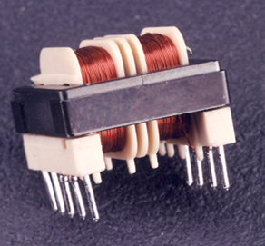
Considering a typical transformer to drive this topic to closure, you may find that the leads are very repeatable, but the molded plastic bobbin is only controlled to a very generous tolerance. We have seen as much as 0.030” lead position variance all due to the bobbin. This is further exaggerated by the bulk packaging or egg carton packaging, keeping in mind that the higher the mass to be shipped, the greater the requirement for segmentation and protection.
The automation machine can have a big impact on the success of the insertion process. The more accurate the machine is, the greater the tolerance can be afforded in the component quality. Further, the automation tool should be equipped with vision to analyze the lead condition prior to insertion. The best machines on the market can inspect and measure the entire array of leads to find the best fit before insertion.
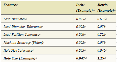
The following is a chart that lists the general considerations, when following this chart, the final number should be considered for the soldering process.
If you find this article helpful and would like to know more, you may contact Stan Earley (Marketing Manager of Automation Solutions in Universal Instruments) by +1-607-725-5129 or earleys@uic.com. You can also go to our website https://www.uic.com/solutions/automation/ for more information on Automation.